Blinking LED on Raspberry Pi using Python
Blinking LED
Raspberry Pi
Python

In this article will make a LED blinking using Python. If you want to see the same circuit in other programming languages, please check the references section.
Components
- 1 * Raspberry Pi (I am using Raspberry Pi 3 Model B)
- 1 * 220Ω Resistor
- 1 * LED
- 1 * Breadboard
- 2 * Jumper wires
- software: GPIO
Note: you can easily find all components on Amazon or Ebay (in my case, I bought a "Raspberry Pi starter kit" containing a lot of components).
LED
The LED is the abbreviation of light emitting diode. The LED has two electrodes, a positive electrode and a negative electrode. It lights up only when a forward current passes. The colour of light depends on the materials it is made. In general, the drive current for LED is really low, between 5-20mA. Usually, needs an extra resistor for the current limitation to protect the LED.
The symbol for a LED is:
There are two methods for connecting a LED with Raspberry Pi GPIO:
- The cathode connected to the Raspberry Pi GPIO.
The anode of the LED is connected to VCC (+3.3V), and the cathode to the Raspberry Pi GPIO. When the GPIO outputs a low level, the LED is on; when it outputs high, the LED is off.
- The anode connected to the Raspberry Pi GPIO.
The anode of LED is connected to Raspberry Pi GPIO after a resistor, and the cathode is connected to ground (GND). When the GPIO outputs a high level, the LED is on; when it outputs a low level, the LED is off.
Resistor
The main function of the resistor is to limit current. In the circuit, the character "R" represents resistor, and the unit of resistance is ohm(Ω).
The symbol for a resistor is:
A band resistor is used in this tutorial. It is a resistor with a surface coated with some particular colour through which the resistance can be identified directly.
To calculate the resistor value needed for this tutorial will use Ohm law:
R=U/I
We already know that to make a LED on a current between 5~20mA is needed. We also know that Raspberry Pi GPIO is 3.3V. Adding these two pieces of information in Ohm Law we can see that a resistor with a value between 165Ω and 660Ω is needed.
R = U / I = 3.3V / (5~20mA) = 3.3V / (0.005A ~0.020A) = 165Ω~660Ω
I have a 220ohm resistor in hand, so I will use it for this tutorial.
Schematics
To do the schematics I used Fritzing software.
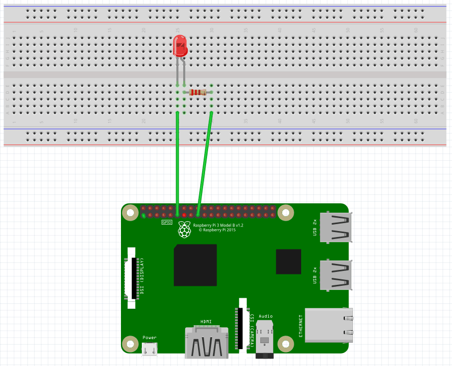
The cathode connected to the Raspberry Pi GPIO
Here is the schematic connecting the cathode of the LED to the Raspberry Pi GPIO. Using the Pinout website for reference, we can see that we connected the LED cathode to the physical pin 11(BCM pin 17, Wiring Pi pin 0)
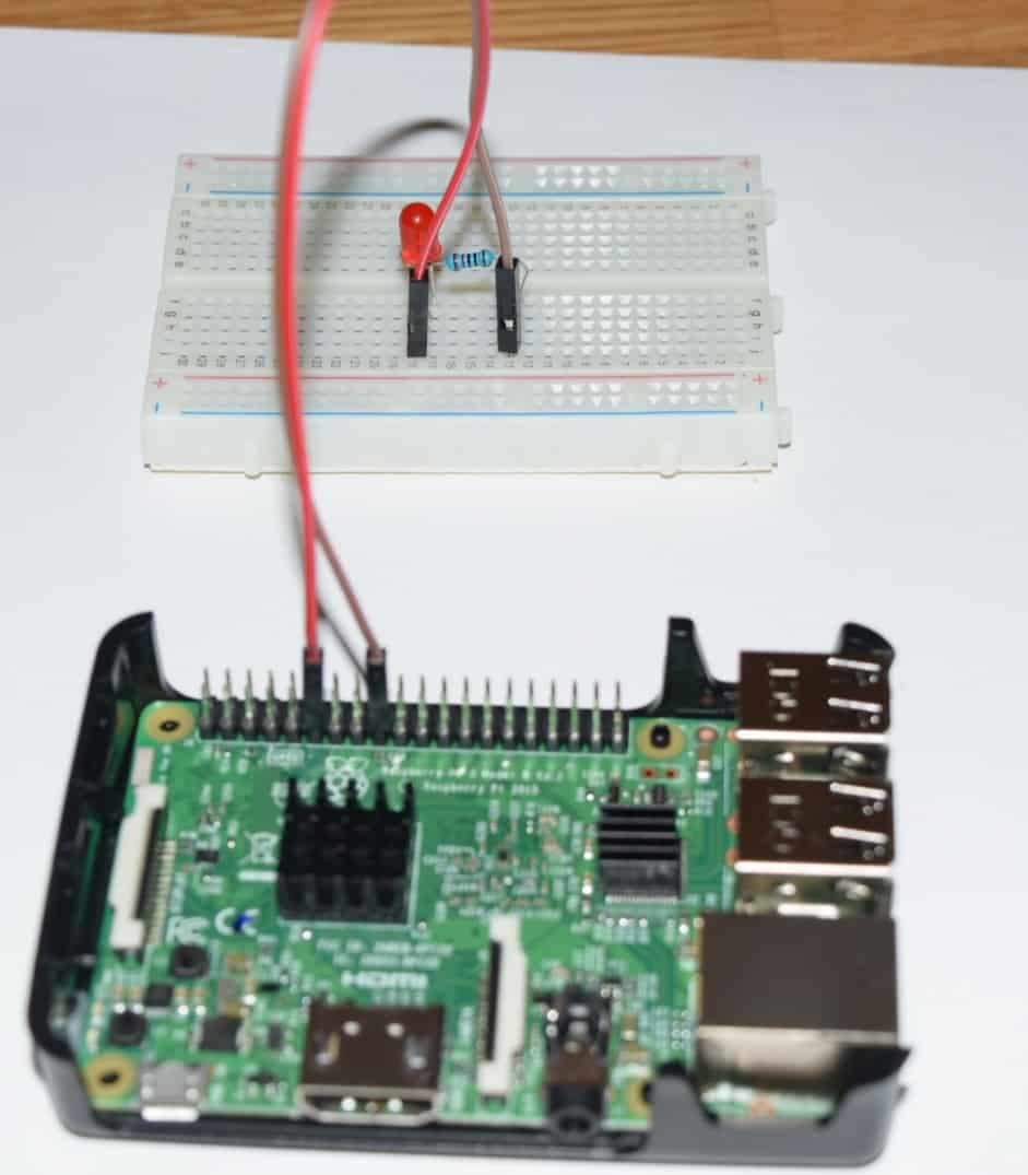
And the physical visualisation of the circuit.
The anode connected to the Raspberry Pi GPIO
Here is the schematic connecting the anode of the LED to the Raspberry Pi GPIO. As you can see the change is just how the connected are placed.
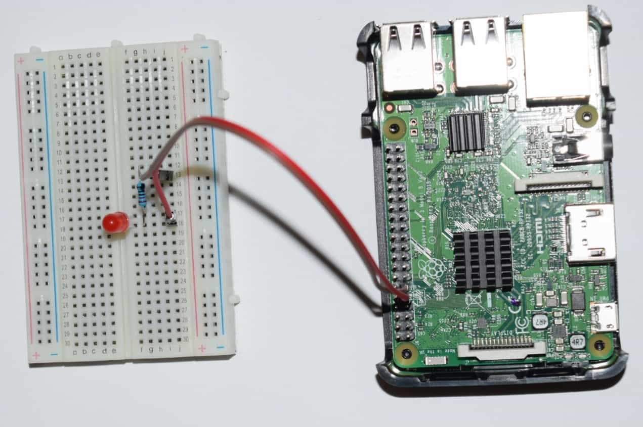
And the physical visualisation of the circuit.
Hardware
Now it's time to connect everything according to the diagram presented in the section above.
The cathode connected to the Raspberry Pi GPIO
The anode connected to the Raspberry Pi GPIO
You can see that the only difference is how it is connected to the board.
Software
Key functions
-
GPIO.setmode(GPIO.BOARD)There are two ways of numbering the IO pins on a Raspberry Pi within RPi.GPIO. The first is using the BOARD numbering system. This refers to the pin numbers on the P1 header of the Raspberry Pi board. The advantage of this numbering system is that your hardware will always work, regardless of the board revision of the RPi. You will not need to rewire your connector or change your code.
The second numbering system is by the BCM(GPIO.BCM) numbers. This is a lower level way of working - it refers to the channel numbers on the Broadcom SOC. You have to always work with a diagram about which channel number goes to which pin on the RPi board. Your script could break between revisions of Raspberry Pi boards.
-
GPIO.setup(channel, mode)The function sets every channel you are using as input(GPIO.IN) or output(GPIO.OUT).
-
GPIO.output(channel, state)The function sets the output state of a GPIO pin. The argument channel is the channel number based on the numbering system you have specified (BOARD or BCM). The state can be 0 / GPIO.LOW / False or 1 / GPIO.HIGH / True.
-
GPIO.cleanup( )At the end any program, it is a good practice to clean up all the resources you might have used. This is no different from RPi.GPIO. By returning all channels you have used back to input without pulling up/down, you can avoid accidental damage to your RPi caused by pin shortcut. Note that this will only clean up GPIO channels that your script ever has used. And it also clears the pin numbering system in use.
Note: all the code will be written directly on Raspberry PI console using vim editor. I've chosen this method because the example is simple and doesn't require a long time to edit. A better approach is to edit the source code locally, on your PC, using your preferable editor and then upload the code to Raspberry PI.
Login to Raspberry PI using ssh command from Linux and MacOS or using putty from windows, then open the vim editor using the following command:
$ sudo vim blinkingLed.pyCopy/paste the following code.
#!/usr/bin/env python
import RPi.GPIO as GPIO
import time

LedPin = 11    # pin11

def setup():
        GPIO.setmode(GPIO.BOARD)       # Set the board mode to numbers pins by physical location
        GPIO.setup(LedPin, GPIO.OUT)   # Set pin mode as output
        GPIO.output(LedPin, GPIO.HIGH) # Set pin to high(+3.3V) to off the led

def loop():
        while True:
                print 'led on'
                GPIO.output(LedPin, GPIO.LOW)   # led on
                time.sleep(1.0)                 # wait 1 sec
                print 'led off'
                GPIO.output(LedPin, GPIO.HIGH)  # led off
                time.sleep(1.0)                 # wait 1 sec
def destroy():

        GPIO.output(LedPin, GPIO.HIGH)     # led off
        GPIO.cleanup()                     # Release resource

if __name__ == '__main__':     # Program start from here
        setup()
        try:
                loop()
        except KeyboardInterrupt:  # When 'Ctrl+C' is pressed, the destroy() will be  executed.
                destroy()
Save and close vim.
Note: if you are new to Python pay attention to the TAB chars. Are very important and are used to group the instructions into blocks.
Test
To run the application execute the following command:
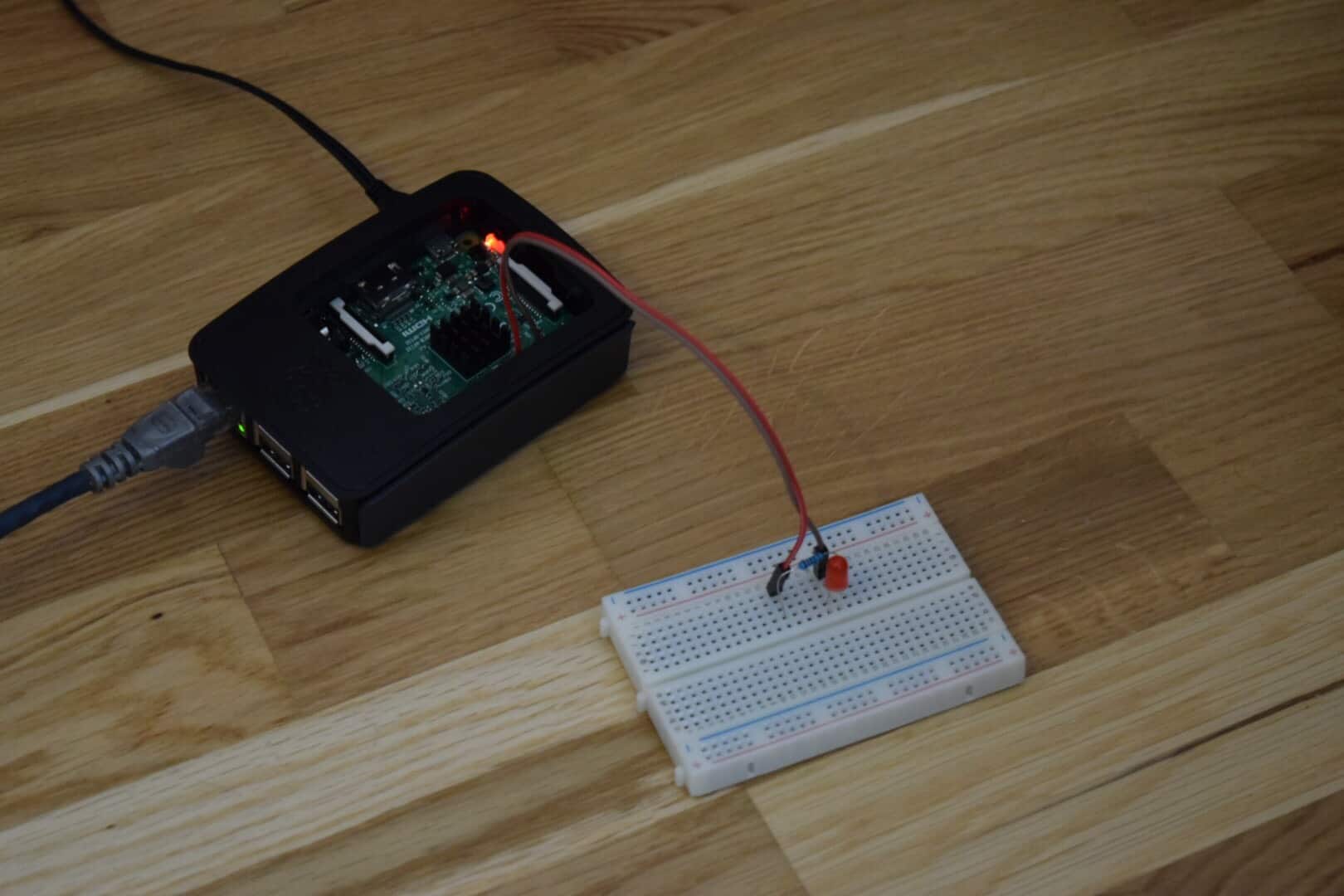
$ sudo python blinkingLed.pyRegarding how you connect the LED, you should see the LED blinking, one second ON, one second OFF. The only difference is:
- when the cathode is connected to the Raspberry Pi GPIO the text printed in the console will correspond with the LED state.
- when the anode is connected to the Raspberry Pi GPIO the text printed in the console will not correspond with the LED state: When is printed "led on" will be actual off.
References
- Fritzing software used in this article to generate the schematic and all images.
- Pinout interactive website.
- Blinking LED on Raspberry Pi using C
- Blinking LED on Raspberry Pi using Java
- Blinking LED on Raspberry Pi using golang


