Blinking LED on Raspberry Pi using Golang
Blinking LED
Raspberry Pi
go-rpio

In this article will make a LED blinking using Go programming language. If you want to see the same circuit in other programming languages, please check the references section.
Components
- 1 * Raspberry Pi (I am using Raspberry Pi 3 Model B)
- 1 * 220Ω Resistor
- 1 * LED
- 1 * Breadboard
- 2 * Jumper wires
- software: go-rpio
Note: you can easily find all components on Amazon or Ebay (in my case, I bought a "Raspberry Pi starter kit" containing a lot of components).
LED
The LED is the abbreviation of light emitting diode. The LED has two electrodes, a positive electrode, and a negative electrode. It lights up only when a forward current passes. The color of light depends on the materials it is made. In general, the drive current for LED is really low, between 5-20mA. Usually, needs an extra resistor for the current limitation to protect the LED.
The symbol for a LED is:
There are two methods for connecting a LED with Raspberry Pi GPIO:
- The cathode connected to the Raspberry Pi GPIO.
The anode of the LED is connected to VCC (+3.3V), and the cathode to the Raspberry Pi GPIO. When the GPIO outputs a low level, the LED is on; when it outputs high, the LED is off.
- The anode connected to the Raspberry Pi GPIO.
The anode of LED is connected to Raspberry Pi GPIO after a resistor, and the cathode is connected to ground (GND). When the GPIO outputs a high level, the LED is on; when it outputs a low level, the LED is off.
Resistor
The main function of the resistor is to limit current. In the circuit, the character "R" represents resistor, and the unit of resistance is ohm(Ω).
The symbol for a resistor is:
A band resistor is used in this tutorial. It is a resistor with a surface coated with some particular color through which the resistance can be identified directly.
To calculate the resistor value needed for this tutorial will use Ohm law:
R=U/I
We already know that to make a LED ON, a current between 5~20mA is needed. We also know that Raspberry Pi GPIO is 3.3V. Adding these two pieces of information in Ohm Law we can see that a resistor with a value between 165Ω and 660Ω is needed.
R = U / I = 3.3V / (5~20mA) = 3.3V / (0.005A ~0.020A) = 165Ω~660Ω
I have a 220ohm resistor in hand, so I will use it for this tutorial.
Schematics
To do the schematics I used Fritzing software.
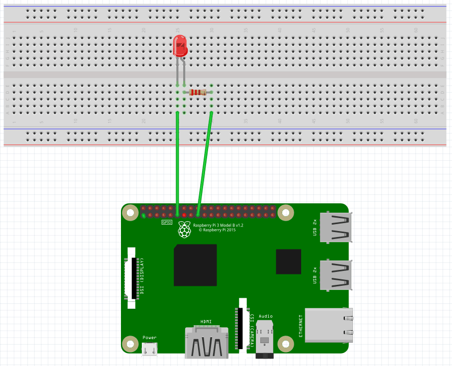
The cathode connected to the Raspberry Pi GPIO
Here is the schematic connecting the cathode of the LED to the Raspberry Pi GPIO. Using the Pinout website for reference, we can see that we connected the LED cathode to the physical pin 11(BCM pin 17, Wiring Pi pin 0)
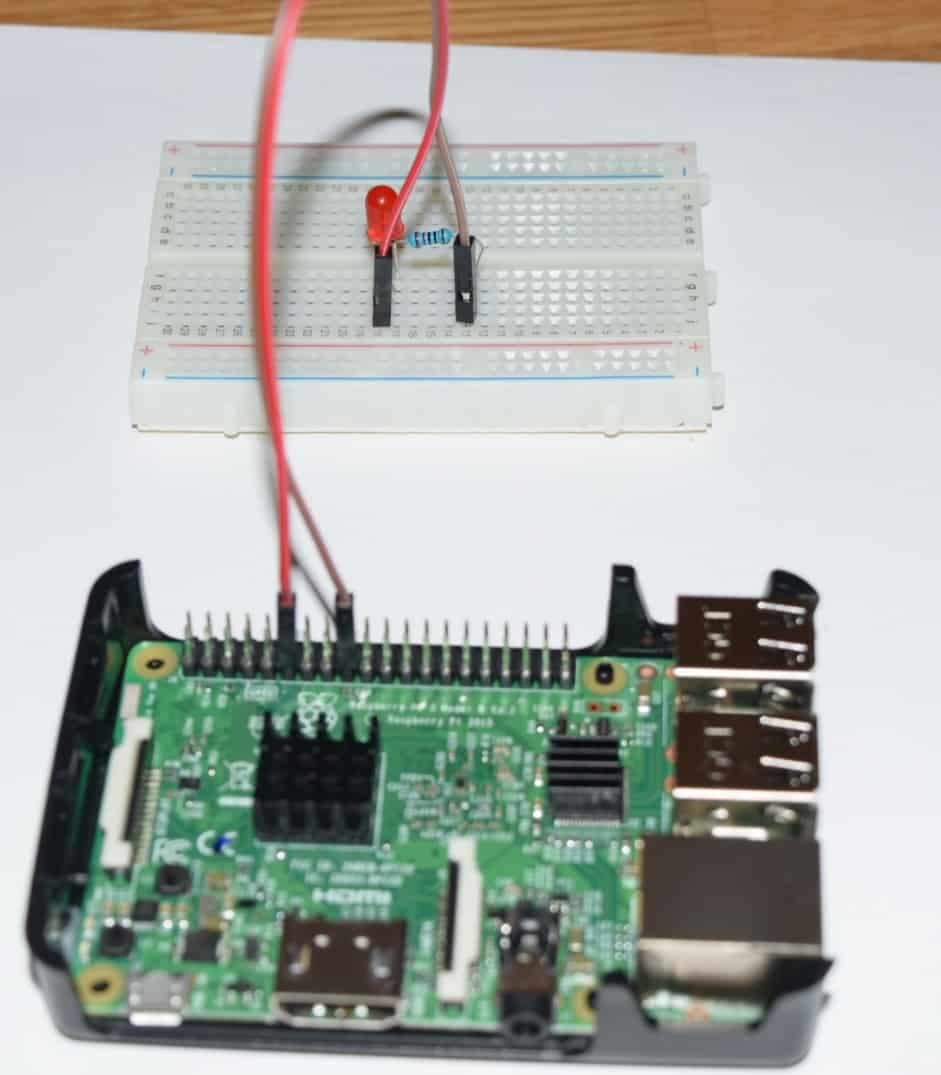
And the physical visualization of the circuit.
The anode connected to the Raspberry Pi GPIO
Here is the schematic connecting the anode of the LED to the Raspberry Pi GPIO. As you can see the change is just how the connected are placed.
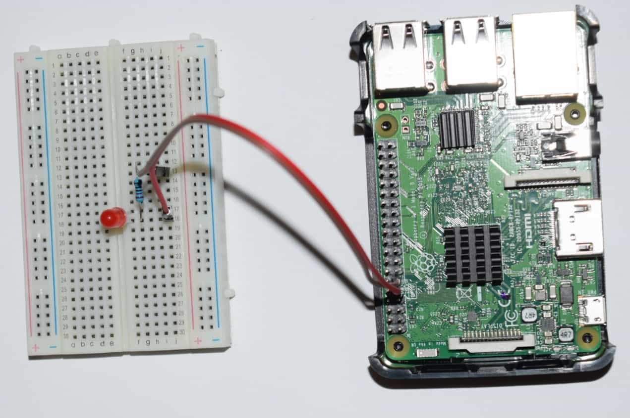
And the physical visualization of the circuit.
Hardware
Now it's time to connect everything according to the diagram presented in the section above.
The cathode connected to the Raspberry Pi GPIO
The anode connected to the Raspberry Pi GPIO
You can see that the only difference is how it is connected to the board.
Software
Note: all the code will be written directly on Raspberry PI console using vim editor. I've chosen this method because the example is simple and doesn't require a long time to edit. A better approach is to edit the source code locally, on your PC, using your preferable editor and then upload the code to Raspberry PI.
Login to Raspberry PI using ssh command from Linux and MacOS or using putty from windows, then open the vim editor using the following command:
$ sudo vim blinkingLed.goCopy/paste the following code.
package main

import (
        "fmt"
        "github.com/stianeikeland/go-rpio"
        "os"
        "time"
)

var (
        pin = rpio.Pin(17)
)

func main() {
        // Open and map memory to access gpio, check for errors
        if err := rpio.Open(); err != nil {
                fmt.Println(err)
                os.Exit(1)
        }

        // Unmap gpio memory when done
        defer rpio.Close()

        // Set pin to output mode
        pin.Output()

        // Toggle - infinite loop
        for {
                pin.Toggle()
                time.Sleep(time.Second)
        }
}
Save and close vim.
Note: The numbering from the go-rpio library is using BCM numbering, physical pin 11 is BCM 17.
Test
First, you need to copy locally the dependency:
$ sudo go get github.com/stianeikeland/go-rpioTo compile the code run the following command:
$ sudo go build blinkingLed.goTo run the application execute the following command:
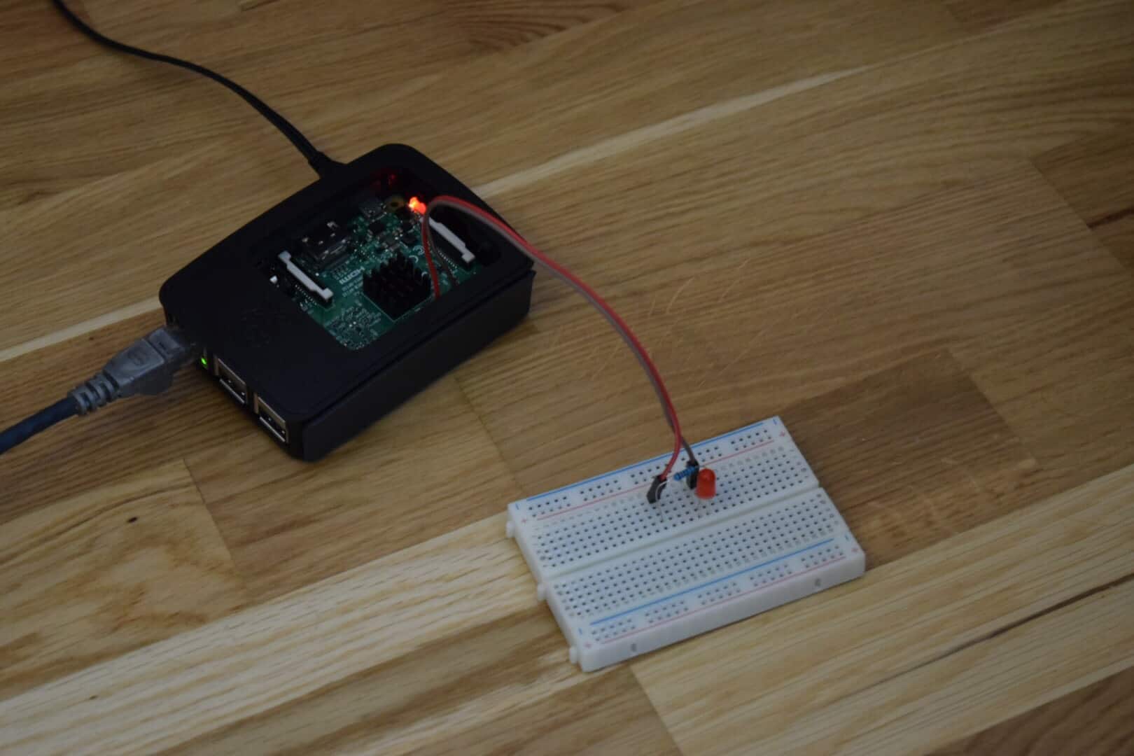
$ sudo ./blinkingLedRegarding how you connect the LED, you should see the LED blinking, one second ON, one second OFF.
References
- Fritzing software used in this article to generate the schematic and all images.
- Pinout interactive website.
- Pi4j library
- Blinking LED on Raspberry Pi using C
- Blinking LED on Raspberry Pi using Python
- Blinking LED on Raspberry Pi using Java


