RGB LED on Raspberry Pi using C
rgb led
raspberry pi
c
WiringPi

In this article will make RGB LED to change colors using Raspberry Pi and C. The LED will change 8 different colors.
The colors used are:
| Color name | Hex Value | Color |
| Red | 0xFF0000 | |
| Green | 0x00FF00 | |
| Blue | 0x0000FF | |
| Yellow | 0xFFFF00 | |
| Cyan | 0x00FFFF | |
| Pink | 0xFF00FF | |
| White | 0xFFFFFF | |
| Violet | 0x9400D3 |
RGB LED
The LED is the abbreviation of light emitting diode. The LED has two electrodes, a positive electrode and a negative electrode. It lights up only when a forward current passes. The RGB LEDs consist of three LEDs in different colors: red, green and blue. These three colored LEDs are capable of producing any color. Tri-color LEDs with red, green, and blue emitters, in general use a four-wire connection with one common lead (anode or cathode).
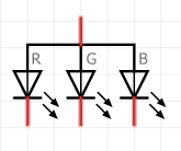
The symbol for common anode RGB LED:
the symbol for common cathode RGB LED:
For this tutorial will going to use a common anode RGB LED.
Components
You will need the following components:
- 1 * Raspberry Pi (I am using Raspberry Pi 3 Model B)
- 3 * 220Ω Resistor
- 1 * RGB LED
- 1 * Breadboard
- 4 * Jumper wires
- software: WiringPi
Note: you can easily find all components on Amazon or Ebay (in my case, I bought a "Raspberry Pi starter kit" containing a lot of components).
Schematics
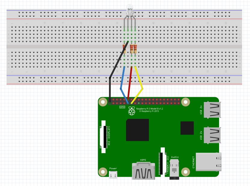
To do the schematics I used Fritzing software. The longest pin is the common anode of the three LEDs. The pin is connected to the +3.3V pin of the Raspberry Pi, and the rest pins are connected to pin 11, pin 12, and pin 13 of Raspberry Pi with a current limiting resistor between (220Ω). Using these pins, we can control the color of the RGB LED by 3-channel PWM signal. If you need more details on PWM, please check Breathing Light LED on Raspberry Pi using C tutorial. Here is the schematics.
And the physical visualization of the circuit.
Hardware
Now it's time to connect everything according to the diagram presented in the section above.
Software
Key functions
-
int softPwmCreate (int pin, int initialValue, int pwmRange)This creates a software-controlled PWM pin. You can use any GPIO pin and the pin numbering will be that of the wiringPiSetup() function you used. Use 100 for the pwmRange, then the value can be anything from 0 (off) to 100 (fully on) for the given pin.
The return value is 0 for success. Anything else and you should check the global errno variable to see what went wrong.
-
void softPwmWrite (int pin, int value)This updates the PWM value on the given pin. The value is checked to be in-range and pins that haven't previously been initialized via softPwmCreate will be silently ignored.
Note: all the code will be written directly on Raspberry PI console using vim editor. I've chosen this method because the example is simple and doesn't require a long time to edit. A better approach is to edit the source code locally, on your PC, using your preferable editor and then upload the code to Raspberry PI.
Login to Raspberry PI using ssh command from Linux and MacOS or using putty from windows, then open the vim editor using the following command:
$ sudo vim rgbLed.cCopy/paste the following code.
#include <wiringPi.h>
#include <softPwm.h>
#include <stdio.h>

#define LedPinRed    0
#define LedPinGreen  1
#define LedPinBlue   2

const int colors[] = {0xFF0000, 0x00FF00, 0x0000FF, 0xFFFF00, 0x00FFFF, 0xFF00FF, 0xFFFFFF, 0x9400D3};

int map(int x, int in_min, int in_max, int out_min, int out_max)
{
	return (x -in_min) * (out_max - out_min) / (in_max - in_min) + out_min;
}

void ledInit(void)
{
	softPwmCreate(LedPinRed,  0, 100);  //create a soft pwm, original duty cycle is 0Hz, range is 0~100
	softPwmCreate(LedPinGreen,0, 100);
	softPwmCreate(LedPinBlue, 0, 100);
}

void ledColorSet(int color)        //set color, for example: 0xde3f47
{
	int r_val, g_val, b_val;

	r_val = (color & 0xFF0000) >> 16;  //get red value
	g_val = (color & 0x00FF00) >> 8;   //get green value
	b_val = (color & 0x0000FF) >> 0;   //get blue value

	r_val = map(r_val, 0, 255, 0, 100);    //change a num(0~255) to 0~100
	g_val = map(g_val, 0, 255, 0, 100);
	b_val = map(b_val, 0, 255, 0, 100);

	softPwmWrite(LedPinRed,   100 - r_val);  //change duty cycle
	softPwmWrite(LedPinGreen, 100 - g_val);
	softPwmWrite(LedPinBlue,  100 - b_val);
}

int main(void)
{
	int i;

	if(wiringPiSetup() < 0) { //when initialize wiringPi failed, print message to screen
		printf("setup wiringPi failed !\n");
		return -1;
	}

	ledInit();

	while(1) {
		for(i = 0; i < sizeof(colors)/sizeof(int); i++) {
			ledColorSet(colors[i]);
			delay(1000);
		}
	}
	return 0;
}
Test
To compile the application run the following command:
$ gcc rgbLed.c -o rgbLed -lwiringPiThe parameter "-o" is to specify a file name for the compiled executable program.
To run the application execute the following command:
$ sudo ./rgbLedNow you should see the RGB LED flashing colors, based on the list provided.
References
- Fritzing software used in this article to generate the schematic and all images.
- Pinout interactive website.
- RGB LED on Raspberry Pi using Python
- RGB LED on Raspberry Pi using Java


